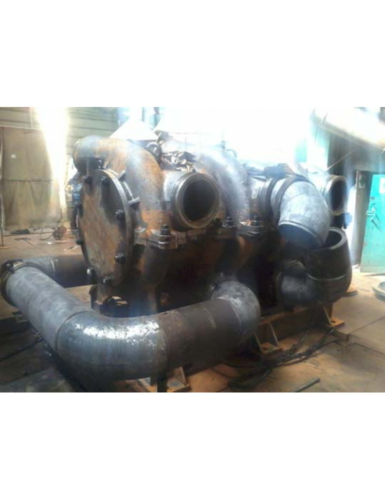
Uglasses of the type 80gd and their basis, designed to pump a coal pulp from mines with hydraulic coal prey and for hydro -vehicles on the surface to the enrichment factory and consumer.
Uglasses and units can be exported to countries with moderate, cold and tropical climate and current frequency of the power network 50Hz.
Pumps belong to the products of a particular purpose (ICN) of the type 1 (restored) in accordance with GOST27.003. The symbol of the pumps in accordance with the structural scheme of the symbol.
design
Units consist of
- pump,
- electric motor,
- connecting coupling, as well as
- Automation and Kip set.
Ugles:
- centrifugal,
- Horizontal,
- one -corps,
- sectional,
- with the end connector of the section in the horizontal plane,
- with an oncoming location of the working wheels.
The direction of rotation of the pump rotor is clockwise if you look from the side of the drive end of the pump.
The pumps of the pump are directed horizontally in opposite directions. The location of the input and pressure pipe is relative to each other depending on the required parameters of the pump (connection diagrams). The flanges of the supply and pressure pipeline, as well as translated pipes are attached to the pump using BRS (rapidly parting).
The sections are two corps parts (housing and cover) with a end connector in a horizontal plane and with a spiral outline and a semi -spiral cart for two wheels. The seal of the plane of the connector is carried out using a steam laying. The sealing force is created by studs located on the plane of the connector. In the upper half of the cover of each section of the pump, an observation hatch is provided.
The sections are interconnected by means of cone-flange connection with a seal of a rubber ring. Speech pumped with liquid from step to steps is carried out by means of translated pipes.
The ugles has bilateral supports that are the rolling bearings on liquid lubricant. They are structurally executed and installed on brackets. The bearing housing has three regulatory screws that give the ability to install the rotor in the middle position. Then they are attached to the housing and fixed with pins. The bearing body does not have a horizontal connector.
The design provides for the cooling of bearing nodes with a pumped medium. Bearing housings are sealed with rubber cuffs. The terminal seals of theormal -type rotor with a hydraulic shutter. The pump rotor is a separate assembly element. The torque from the shaft is transmitted to the working wheels by means of a conical connection. The axial force acting on the rotor is unloaded by the counter location of the working wheels.
The residual unbalanced force is perceived by double radial-wrapped bearings, which simultaneously fix the position of the rotor in the pump. Inter -stage seals of the slotted type.
Installation of the pump on the frame is carried out using paws (2 paws per section) located in the lower part of each section.
| Designation | Feed, m 3 /h | Ples, m | Poyal power, kW (ρ = 1061kg/m 3 ), |
| 80gd700/600 | 700 | 600 | 1867 |
| 80gd1400/300 | 1400 | 300 | 1867 |
| 80gd2100/200 | 2100 | 200 | 1867 |
| 80gd4200/100 | 4200 | 100 | 1867 |
| 80gd700/400 | 700 | 400 | 1245 |
| 80gd1400/200 | 1400 | 200 | 1245 |
| 80gd2800/100 | 2800 | 100 | 1245 |
| 80gd700/200 | 700 | 200 | 622 |
| 80gd1400/100 | 1400 | 100 | 622 |


